Visual Elements Menu
- Lines
- Polygons
- Assign textures to polygons
- Load & remove textures
- Check Texture-specific Background Colors on Polygons
-
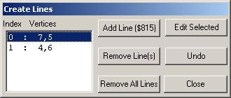
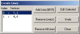
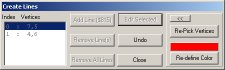
Lines
Use this function to define Lines, which are used
as wires etc. in a 3DO.
To add a new 3DO line, use the [Add Line] button.
Next step is to choose a color for the line in the
color dialog.
Note: Unlike with Polygons, the color of the Line
is the actual color in GPL !
After the color is defined, the Cursor changes to
a "Pointing Hand" symbol.
Use the Mouse to pick the two vertices which make
up the Line.
The newly created line will be shown in the table.
It is also shown immediately in the display window.
This procedure can now be repeated to add more Lines.
By clicking on a line in the table, it becomes selected
and the [Edit Selected] button becomes enabled, allowing modifications
of the selected line(s).
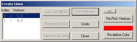
Note: More than one Line can be selected
and edited at once, but only the color of the selected Line(s) can be modified
then.
When a single Line is selected, the vertices
can be re-defined also.
All Selected Lines are shown as dotted lines.
Selected Lines become unselected only when the Line
Dialog is closed.
- Remove All Lines
This removes all Lines at once.
- Remove Line(s)
This removes all currently selected Lines.
- Undo
Undo restores the last action and can be
used even after the Line dialog was closed and re-opened.
Top of page
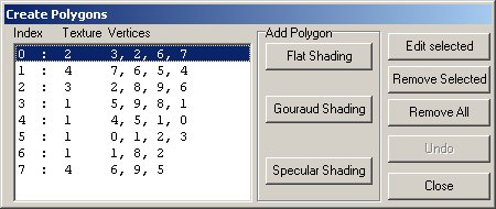
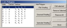
- Polygons
Use this function to define Polygons.
To add a new 3DO Polygon, use the [Flat Shading]
button under 'Add Polygon'.
Depending on the settings in Options, the next step
is to choose a color for the line in the color dialog.
Note: The color of the Polygon is NOT the actual
color in GPL, it is only there for visualzation !
The final (untextured) color of the polygon is defined by
the background color of it's texture !
The Cursor changes to a "Pointing Hand" symbol.
Use the Mouse to pick the vertices which make up
the Polygon. To close the Polygon, select the FIRST vertex again !
Note: The polygons have to be drawn clockwise
facing the the user, otherwise the backside appears in GPL, which is usually
not wanted.
With a rectangle (4 vertices), it is best to
rotate the scene so the required vertices face the user, then start picking
the vertices from lower left, upper left, upper right, then lower right.
Then the lower left vertex has to be picked again to close the polygon.
The newly created polygon will be shown in the table.
It is also shown immediately in the display window.
This procedure can now be repeated to add more Polygons.
By clicking on a polygon in the table, it becomes
selected and the [Edit Selected] button becomes enabled, allowing modifications
of the selected Polygon(s).

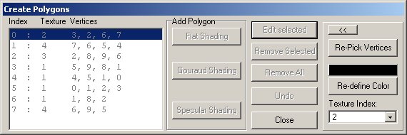
Note: More than one Polygon can be selected
and edited at once, but only the color and the texture index of the selected
Polygon(s) can be modified then.
When a single Polygon is selected, the vertices
can be re-defined also.
All Selected Polygons are shown with a random color
frame around them.
Selected Polygons become unselected only when the
Polygon Dialog is closed.
- Remove All
This removes all Polygons at once.
-
Remove Selected
This removes all currently selected Polygons.
-
Undo
Undo restores the last action and can be
used even after the Polygon dialog was closed and re-opened.
Top of page
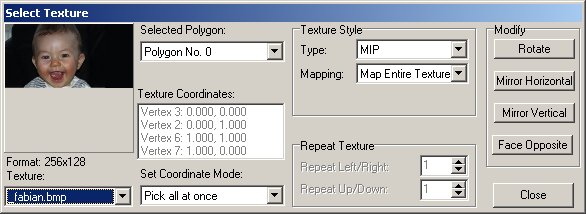
- Assign Textures to Polygons
Use this function to map textures onto polygons.
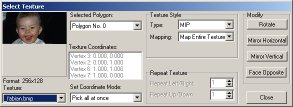
- Selected Polygon
This sets the polygon to texturize.
- Texture
Choose the texture to map onto the selected polygon.
If no texture is loaded yet, select "-> Load New Texture" to add a new texture to the project via the Load & Remove textures dialog.
When done, reselect that new texture from the this list.
- Texture Style
Type: Choose MIP or SRB for the type of Texture file. MIP is default, which is easy, as SRB is not supported for now ;-)
Mapping: Map either the entire texture, parts of it (points need to be picked) or repeated (tiled).
- Repeat Texture
These values define how many times the texture is repeated left/right and up/down (Only possible when Mapping > Repeat Texture is set).
- Modify
Rotate: Rotates the texture edge-by-edge (NOT in degrees).
Mirror Horizontal: Mirrors the texture around the horizontal axis.
Mirror Vertical: Mirrors the texture around the vertical axis.
Face Opposite: Makes the texture visible from the other side.
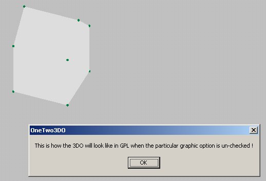
This is useful when the direction of the polygon is the wrong way.
With certain textures, the result of this function is sometimes hard to tell.
However, it can easily be controlled when Show Polygon Backfaces is un-checked in Options.
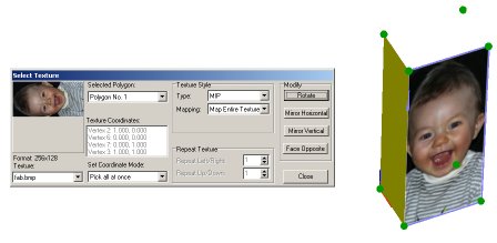
This example shows an entire textured polygon where the rotate function has been used.
Note how the original texture is lying on the side (256 wide/128 high),
but the texture on the polygon is rotated to appear upright.
- Texture Coordinates
This list shows the texture coordinates of the polygon's vertices. Is is disabled whenever Map Entire Texture and Repeat Texture is used, because those two automatically set the coordinates.
When Map Texture Area is used, double-clicking into the list defines the texture coordinates, depending on the settings of Pick Coordinate Mode.
One click into the list highlights the particular vertex.
- Pick Coordinate Mode
These values define what happens after a double-click into the coordinate list.
Pick all at once: Opens a window with the chosen texture where one after another texture coordinate has to be picked using the mouse.
Pick single: Only the vertex which was clicked in the list has to be picked.
Manually: Type the values in edit boxes for the vertex which was clicked in the list.
Load from File: Loads texture coordinates from a file (currently not available).
Top of page
- Load & Remove Textures
Use this function to load textures into the project. Polygons are textured using Bitmap files.
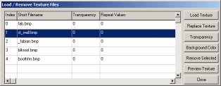
To add a new Texture, use the [Load Texture] button.
The new Texture is then shown in the table. Meaning of the columns:
- Index
The reference number of the Texture
- Short Filename
The filename of the Texture (which is also the reference STRN name in the 3DO)
- Transparency
0 = Texture is transparent, 1 = Texture is not transparent (see below)
- Repeat Value
If texture is repeated, where 0= No, 1= Horizontal, 2= Vertical, 3= Both
- Filename
The long filename (incl. full path)
- Mask Filename
The long filename (incl. full path) of the mask file (if Texture is transparent)
To replace the selected texture with a new Texture, use the [Replace Texture] button.
To make a selected texture transparent, use the [Transparency] button.
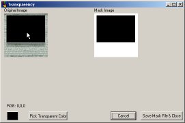
Use the [Pick Transparent Color] button to define the masking color in the original image. The masked image is then displayed accordingly. Also, the color is shown on the lower left, together with it's RGB values.
The mask file can then be saved and used for masking a MIP with MipMan etc.
Note: It is strongly recommended to save with the default value and give a filename- ending
like 'originalbitmap'_mask.bmp. This way one can tell which is the original and which is the appropriate mask bitmap
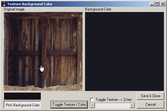
To change the background color of the selected texture, use the [Background Color] button.
The background color of the texture is the color that is seen within GPL when the particular graphic
option is un-checked and the polygon(s) appear un-textured. The default value is grey.
The use of this function is quite similar to
the Transparency function.

Use the [Pick Background Color] button to define the background color in the original image.
The background color is then displayed accordingly.
Use the [Toggle Texture/Color] button to switch the right view between texture and color.
Use the check box [Toggle Texture] to automate that. The slider below then defines the switching rate.
- Remove Selected
This removes the currently selected Texture.
-
Preview Texture
Use this function to open and preview another bitmap. The preview-window can be resized.
Note: When selecting a line from the list, the polygons which use this particular texture are highlighted !
Top of page